
CoolingTower:SingleSpeed
CoolingTower:TwoSpeed
CoolingTower:VariableSpeed:Merkel
CoolingTower:VariableSpeed
Used in:
- Condenser loop, supply side
|
|
CoolingTower:SingleSpeed CoolingTower:TwoSpeed CoolingTower:VariableSpeed:Merkel CoolingTower:VariableSpeed |
Used in:
|
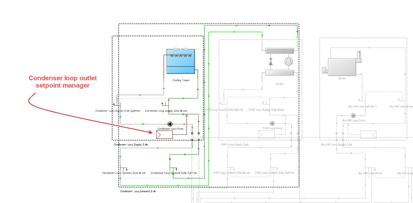
Cooling towers are placed on the supply side of condenser loops. The cooling tower is modelled as a counter-flow heat exchanger with options for single-speed, two-speed or variable-speed fan. Specifically, 4 types of cooling tower are available:
Cooling towers here are “wet” and consume water through evaporation, drift, and blow-down. The model can be used to predict water consumed by the towers.
The cooling tower seeks to maintain the temperature of the water exiting the cooling tower at (or below) a set point. The set point schedule value is defined by the condenser loop outlet setpoint manager:
 See the Condenser loops cooling tower tutorial
The schematic diagrams below (reproduced with permission from CIBSE) illustrate the various types of Direct & Indirect Heat Rejection used in cooling towers. The condenser process takes the fluid from saturated vapour (point 5) to saturated liquid (point 6) on the graph below.
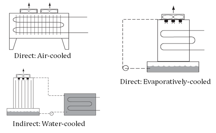
Direct & Indirect Heat Rejection (CIBSE Guide B Table 4.10)
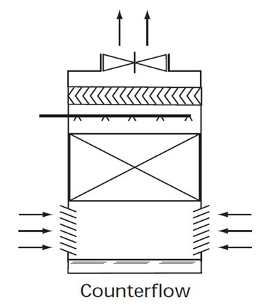
Induced Draft Cooling Tower (CIBSE Guide B Table 4.22)